
Please see below a summary of precautions when using our products.
1.Product Rating Information
- The ratings indicated on our switches show the maximum value for resistive loads (power factor = 1).
- Therefore, if the type of load differs from resistance, the life of the switch will be affected, so please take the characteristics of the load into consideration when using the switch.
2.Types of Loads and their Effects
Resistance Load
- This is the case when the load is resistive only and the power factor (cos Φ) = 1. Even loads that are generally treated as resistive loads often contain an inductive or capacitive component as well as a resistive component, so that the switch should be used at approximately 80% of its rated current, taking the life of the switch into account.
Induced Load
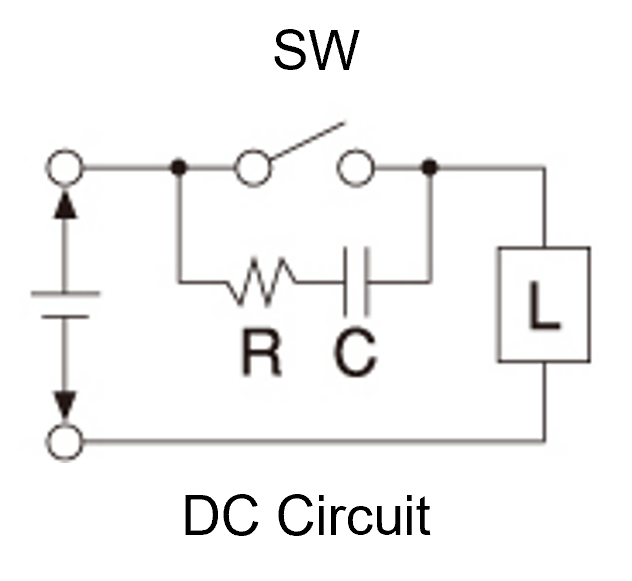
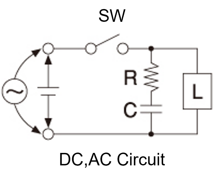
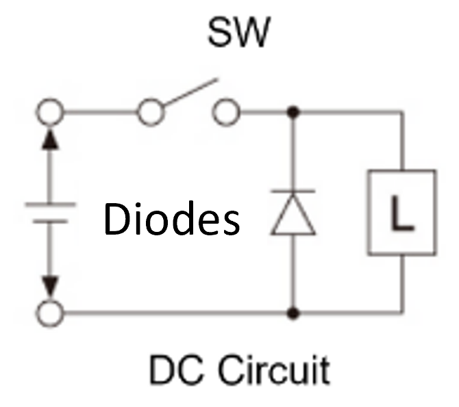
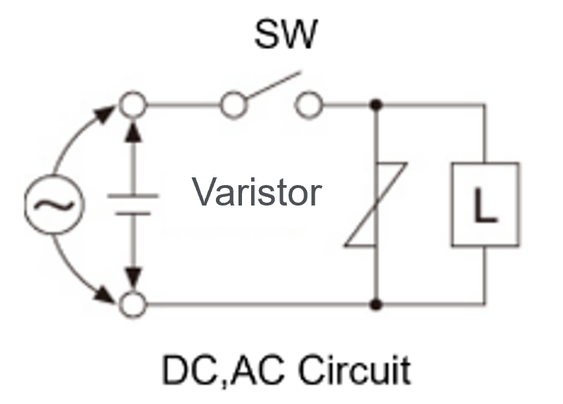
- In the case of inductive loads (relays, motors, solenoids, transformers, etc.), arcs due to large reverse voltages occur when the switch contacts open and close, causing contact wear and transfer and shortening the life of the switch. When used with such inductive loads, it is recommended to insert a contact wear protection circuit as described below.
Motor Loads
- For motor loads, a current (start-up current) of 3 to 8 times the steady-state current flows when the motor starts up. This current value varies depending on the type of motor and can cause welding of the switch contacts, so take the type of motor and its starting current value into consideration. If the switch is used to switch between forward and reverse rotation of the motor, it is recommended to use a switch with ON-OFF-ON type switch characteristics and to stop the motor once and then reverse it. If the motor is reversed while it is running, a current approximately twice the starting current will flow, which may cause the switch contacts to weld together.
| Motor | Type | Start-up Curent |
|---|---|---|
| 3 Phase Induction | Squirrel Cage | 5-8 times stated current |
| Single Phase Induction | Split Phase Start | 6 times stated current |
| Single Phase Induction | Condenser Start | 4-5 times stated current |
| Single Phase Induction | Repulsion Start | 3 times stated current |
Filament Lamp Load
- In the case of filament lamp loads, an inrush current (10 to 15 times the steady-state current) flows when the switch is switched on under lamp cooling conditions, which may cause the contacts to weld due to the heat generated. It is therefore recommended to take this inrush current into account when selecting the switch rating.
DC Load
- In the case of direct current, since there is no voltage fluctuation compared to alternating current (since there is no point at which the voltage and current become zero), a constant voltage is always applied, and even with small loads, a large arc is generated when the load is switched off, easily causing damage to the contact points. Generally, resistive loads of 30V DC or less can be used up to the rated current corresponding to resistive loads of 125 V AC, but DC motors, lamps and inductive loads should be considered as in the case of AC as described above. For switches with a common terminal, connecting the negative pole to the common terminal helps prevent contact damage due to arcing.
Condenser Load
- For capacitor loads, the inrush current at switch-on is theoretically infinite. Therefore, connect a resistor to the series to suppress the peak current. If a resistor is not connected, it may cause welding of the contacts.

| Load Type | Multiplier to rating (usually current) | Ex) AC.125V.10A |
|---|---|---|
| DC | (1) Voltage change approx. 1/5 (current unchanged) (2) Current change approx. 1/10 (voltage unchanged) | (1) DC. 25V. 10A (2) DC. 125V. 1A |
| Filament Lamp | 1/2 to 1/3 times Incandescent bulbs have an inrush current almost 10 times higher than normal. | AC.125V 3~5A |
| Motor | 1/3 times 3-8 times the starting current of the motor | AC.125V. 3A |
| Condenser | The maximum current must be reduced by connecting a resistor | Depends on resistance value (see separate sheet) |
| Inductive | For a power factor of 0.6 Use within 60% of rated value | AC.125V 6A or below |
3.Low Current and Low Voltage Applications
- Switches using silver or silver alloys as contact material and silver-plated switches are susceptible to the formation of oxide films on the contact surface due to the operating environment (mainly corrosive gases) when used in the micro-voltage and micro-current range (voltage and current range where no arcing occurs due to electrical opening and closing).
- This can lead to problems such as increased contact resistance and contact instability. Gold-plated switches are recommended for such use.
4.Illuminated Switches
Neon Bulb Switches
- Illuminated switches with neon bulbs have a built-in resistor for controlling the neon discharge voltage based on the voltage indicated on the switch rating. When using the switch, use it at the voltage indicated on the rating. If the voltage is lower than the rated voltage, the neon bulb will not emit light, will flicker, or the luminous intensity will be reduced.
- Even when no voltage is applied to the neon ball, it may malfunction due to electrostatic fields caused by frictional electric charges, etc. They may also be misdischarged by high-frequency voltage from high-frequency transmitters or electromagnetic induction from electrical circuits, etc. Please pay attention to external conditions such as wiring.
LED Switches
- The switch circuit and the LED circuit are separate circuits. The LED circuit is not connected to a current limiting resistor. Therefore, the LEDs must be supplied with the appropriate DC voltage and current as specified in the operating characteristics table. Use of LEDs with values other than those listed in the operating characteristics table may result in a failure to achieve the correct luminance or a shortened service life. The values in the characteristics table indicate the values when the power supply used is fully DC. Therefore, when using full-wave rectified power supplies or other pulsating current waveforms, make sure that the peak current value does not exceed the forward current IF. If the peak current value exceeds IF, the service life will be reduced.
- Always connect a current limiting resistor R in series with the LED circuit to control the voltage and current applied to the LEDs.

5.Soldering
- Use a non-corrosive rosin solution for the flux.
- Do not use more flux than necessary. It may penetrate inside the switch and cause poor contact.
- Soldering should be carried out within the specified temperature and in a short time. If the temperature is above the specified temperature or for a longer period of time, the insulation may be damaged and the terminals may loosen. The temperature may vary slightly depending on the type of switch, but as a rule of thumb, use a temperature of 270 °C for 3 seconds or less.
- Do not apply any load to the terminals during soldering operations. Do not apply external force within 1 minute after soldering. This may cause the terminals to loosen.
- After soldering, do not clean the product with solvents. Depending on the type of solvent, deterioration of the moulded product may occur. If cleaning is unavoidable, please let us advise.
- Push-button switches with push-ON (OFF-ON momentary) characteristics must be soldered in the OFF state to avoid thermal deformation of the internal components, etc. Soldering in the ON state may cause thermal deformation.
6.Operating Environment
- Avoid using the switch in environments where it is exposed to water, oil, chemicals (including detergents), dust, corrosive gases or high humidity. This will deteriorate the electrical and mechanical performance of the components that make up the switch.
- Use within an ambient temperature range of -10°C to +55°C. If the switch is used outside this range, the strength of the parts may be reduced or malfunctions may occur due to freezing of the grease in a low temperature environment. Also, in high temperature environments, the inside of the switch will naturally be higher than the ambient temperature, which may cause deterioration of the insulation and other phenomena that will significantly shorten the service life of the switch, so please avoid this or consult us first.
- Use in an environment where the atmospheric pressure is lower than normal (atmospheric pressure 86-106 kpa) will reduce the voltage resistance of the air and insulation, resulting in insulation breakdown and an increase in the frequency and amount of arcing when opening and closing contacts, which will shorten contact life.
- Use in an ambient humidity range of 35% to 85%RH. In particular, prolonged use at high humidity may lead to insulation degradation, e.g. due to migration, so please avoid use or consult with us.
- Avoid use in environments subject to severe vibration or impact, as this may cause contact failures or abnormal wear of the components.
7.Storage
- To prevent deterioration of the electrical and mechanical performance of the mechanical components, avoid storage in environments subjected to vibration and shock, corrosive gases, high temperatures and humidity, and dusty environments.
8.Operation
- Do not apply loads or impact forces to the actuator of the switch in excess of the specified operating force. Loads or impact forces in excess of the specified operating force not only impair the performance of the switch, but may also result in its destruction.
- The actuator must always be operated to the specified position to ensure proper contact pressure at the contacts and a reliable switching function of the contacts.
- If the switch is operated by static electricity generated by the human body, which can have an adverse effect on the connected circuit, a switch with an actuator insulated against static electricity is recommended.
9.Mounting
- Mounting dimensions should be determined taking into account the material of the mounting plate, the state of the finish, the mounting position and the workability of the mounting. The mounting dimensions given are therefore to be regarded as reference values only.
- For switches mounted with a nut, fix the switch body and tighten the attached nut to the mounting plate by turning it within the specified tightening torque. Over-tightening the switch body may damage the switch.
- Switches mounted on printed circuit boards should be mounted on the printed circuit board without applying any force that may deform the terminals.
10.Fitting and Removal of Actuators
- When detaching and reattaching the push button (for switches with detachable buttons), be sure to do so in the free (unlocked) state for the alternate type (the ON or OFF state is maintained irrespective of the button operation). Doing so in the locked state may damage the locking mechanism.
11.Care of Plastic Parts
- Do not use alcohol or solvents (including detergents) to clean the plastic part of the switch. This will cause deterioration of the plastic parts, accelerate ageing and increase the likelihood of cracks, splits and breakage.
12.Current Capacity of Minomushi Clips® and IC Test Clips
- Please note that these stated current values do not indicate the values for switching on or off the current. Therefore, these must only be connected or disconnected after the circuit current has been interrupted.
13.Ratings of AC Power Plugs (MC-037)
- The rating indications on AC Power Plugs indicate the maximum value for a load power factor of 0.95 to 1. Therefore, if the load power factor is different, the life of the outlet will be affected, so please take the characteristics of the load into consideration. As a guide, it is recommended to use the outlet at approximately 80% of the rated current.
14.Unplugging the AC Power Plugs (MC-037)
- Always use the correct plug and plug the AC Power Plug perpendicular to the mounting surface to maintain proper contact and to prevent abnormal heat build-up.
15.Product Specifications
- As standards differ for each product, please request individual specifications for further details. In principle, we cannot guarantee the use of products other than those described in the specifications, so please consult us in such cases. If there is any overlap between the individual specifications and this information, the individual specifications shall take precedence.
- Product specifications are subject to change without notice due to product improvements.
16.DS and MS Item Codes
- Products with item codes beginning with "DS" are compliant with Product Safety Electrical Appliance & Material (PSE) law.
- Products with item codes beginning with "MS" may or may not comply with the technical standards of Annex 8 of PSE law, depending on the environment in which the product to be assembled as a switch is used.
- For compliance with the Electrical Appliance and Material Safety Law for products to be incorporated, please check with the certification body or consult with them.